SR520 THRU SR5200
trusTec
200,000pcs
Negotiable (FOB/CNF/CIF)
T/T, L/C
15-30 days fresh products after order confirmation.
200,00000 pcs per month
| Quantity: | |
|---|---|


The plastic package carries Underwriters Laboratory
Flammability Classification 94V-0
Metal silicon junction,majority carrier conduction
Low power loss,high efficiency
High forward surge current capability
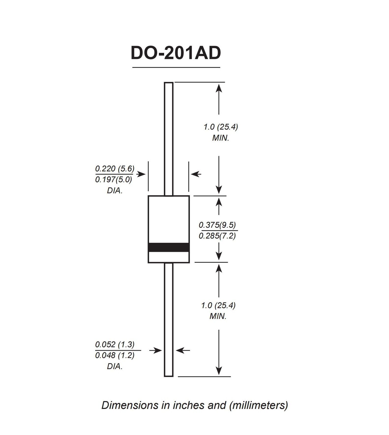
High temperature soldering guaranteed: 260 C/10 seconds,0.375”(9.5mm) lead length, 5 lbs. (2.3kg) tension
Ratings at 25℃ ambient temperature unless otherwise specified.
Single phase half-wave 60Hz,resistive or inductive load,for capacitive load current derate by 20%.
1.Measured at 1MHz and applied reverse voltage of 4.0V D.C.
2.Thermal resistance from junction to ambient at 0.375”(9.5mm)lead length,P.C.B. mounted
The plastic package carries Underwriters Laboratory
Flammability Classification 94V-0
Metal silicon junction,majority carrier conduction
Low power loss,high efficiency
High forward surge current capability
High temperature soldering guaranteed: 260 C/10 seconds,0.375”(9.5mm) lead length, 5 lbs. (2.3kg) tension
Ratings at 25℃ ambient temperature unless otherwise specified.
Single phase half-wave 60Hz,resistive or inductive load,for capacitive load current derate by 20%.
1.Measured at 1MHz and applied reverse voltage of 4.0V D.C.
2.Thermal resistance from junction to ambient at 0.375”(9.5mm)lead length,P.C.B. mounted


